Stepper Motor Driver
The stepper motor interface board was built by Bret Victor for his ditch
day stack. If a stepper motor is ever needed for the Coke machine, well,
we've got one. The reason a PAL is used instead of a 374 is that I had a
ton of 20V8's lying around, so it was cheaper than buying a new chip. There
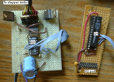
are two boards. The board on the right goes near the controller board, and
is attached via a very long ribbon cable to the board on the left, which
goes near the actual motor. The board near the motor requires an external
power supply (9-12VDC or so, standard barrel connector with center ground).
Chip List
U1: PAL20V8 - latch to store the data bus on write cycles:
latch.pds
U2: LM324 - op-amp to buffer the signals from the PAL.
There are four TIP112 darlington transistors to drive the motor coils, and
of course, protection diodes.
Use
Write a byte to any address to set the stepper motor pattern. Only the
low four bits matter.
Notes
The motor itself has a connector with six wires in the following order:
yellow, brown, grey, green, orange, red. Brown and orange are on either
end of one coil, and green is the center-tap. Yellow and red are on either
end of the other coil, and grey is the center-tap. The motor driver board
is wired with the center-taps attached through resistors to positive voltage,
and the ends of the coils attached to the collectors of the TIP112 power
transistors. There is a protection diode across each half-coil, from coil
end to center-tap.