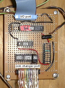
Money I/O board and Coin Changer board
The money I/O board was built by Bret Victor and Jeremy Boulton. This
board allows the controller to determine when change is inserted and
control various aspects of the Coke machine, such as spitting out nickels
and putting the machine into a state where a beverage can be released.
Not pictured above
is the coin changer board which we built as a replacement
for the original circuit board in the Coke machine, and resides inside the
coin changer package. The signals passed between the I/O board and the
coin changer board are opto-isolated, because the coin changer board runs
off of another power source (it has its own transformer) and I didn't want
them to share grounds. Vague, cave-painting-esque
schematics are available. The top
part is the coin changer board and at the bottom is the I/O board (pictured
above). The meanings of the numbers are below. (Note that a wavy line
indicates the wires are being passed through a connector to the other board.)
Chip List
U1: PAL20V8 - controller PAL for I/O and stuff:
money.pds
U2: ULN2003A - transistor pack for reading opto-isolators
U3,4: NTE3220 - dual opto-isolators for signals output to the coin changer
board
U5: ECG3081 - opto-isolator for signal (motor switch) input from the
coin changer board
Use
Only the low four bits of the data bus are used. Read this from any
address (all active high):
bit 3: dime switch
bit 2: nickel switch
bit 1: nickel tube empty switch
bit 0: nickel motor switch
Write this to any address (all active high):
bit 3: "exact change required" light on
bit 2: nickel-spitter motor on
bit 1: purchase pulse
bit 0: CREMs active (money can be accepted)
The nickel motor switch will pulse after each nickel has been
spit out. The purchase pulse bit should be pulsed high and low to put
the machine into a state where the next "button push" will release
a beverage. A quarter being inserted is indicated by both the dime
and nickel bits being high.
Pinouts
In the schematic, the numbers with
circles are on the connector between the I/O board and the coin changer
board. The numbers without circles are on the connector between the coin
changer board and the machinery.
I/O connector pinout (colored ribbon, circled numbers):
- 1,2: Exact Change light
- 3,4: CREMs
- 5,6: Purchase state relay
- 7,8: Nickel release motor
- 9,8: Nickel motor revolution switch
- 15,16: Nickel insertion switch
- 17,18: Dime insertion switch
- 19,20: Nickel tube empty switch
CoinCo connector pinout (row of pins on the coin changer board)
- 20: 120VAC hot
- 19: 120VAC hot
- 18: 120VAC hot
- 17: no connection
- 16: no connection
- 15: output: normally open; short to 120VAC common during purchase pulse
- 14: 120VAC common
- 13: output: normally short to 120VAC common; open during purchase pulse
- 12: 120VAC common
- 11: no connect
- 10: no connect
- 9: input: normally shorted to pin 7; open when nickel inserted
- 8: input: normally shorted to pin 7; open when dime inserted
- 7: input: open when quarter inserted
- 6: input: normally grounded (pin 4); open when motor revolution switch is hit
- 5: output: normally open; drive to ground (pin 4) to make motor turn
- 4: output: ground
- 3: output: +12VDC
- 2: input: one side of "12VAC" (actually more like 20V), from transformer
- 1: input: other side of 12VAC