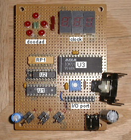
Doodad and Clock Display
The doodad and clock display was built by Peter Maresh. The clock is
driven by a modulo-60 counter, so it can only be used as a clock. The
doodad is a pattern of five red LEDs with a green LED in the center.
There is no schematic, but it should be obvious.
Chip List
U1: 74LS374 - latch to store the data bus on write cycles
U2: ULN2003A - transistor pack to drive the doodad LEDs
U3: Maxim ICM7217B - counter/decoder/driver to drive the numeric clock
display
RP1: 330 ohm resistor pack to limit the current of the doodad LEDs
Use
Write a byte to any address to make stuff happen:
bit 7: clock count (pulse high/low to count up one)
bit 6: green doodad LED, active high
bit 5-1: red doodad LEDs, active high
bit 0: clock /reset, active low (pulse low/high to clear counter to zero)
Notes
The other stuff you see (TO-220, pot, power connector) is a voltage regulator
circuit. It used to be that an transformer was plugged into the connector
(+7VDC or more, center ground) and all boards except the controller were
powered off of this. Now everything runs off of a regulated switching
power supply, so this is unnecessary.