Controller Board
The controller board was built by Steven Ginzburg for an EE/CS 53
project. It is a generic 68HC11-based system board. It
has sixteen expansion ports, on-board RAM and EEPROM, and serial I/O.
The (not quite accurate) schematic is available in pretty color
postscript format:
controller.ps.
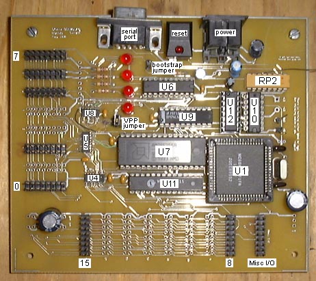
Chip List
U1: 68HC11F1 - microcontroller
U4: 74F138 - port select decoder (8-15)
U5: 74F138 - port select decoder (0-7)
U6: 74LS244 - port address and LED buffer
U7: Am28F256A-90 - 32K x 8 bit EEPROM
U8: 74F125 - random tri-state buffers
U9: 74LS245 - data bus two-way buffer
U10: 74LS00 - NAND gates used as inverters
U11: W24257AK-15 - 32K x 8 bit SRAM
U12: MC145406P - RS232 driver/receiver
Issues
This board has problems. First of all, as you can see from the
schematic, the HC11 data bus D0, D1, D2, D3, etc. is wired to the
external data bus as D7, D0, D1, D2, etc. In other words, the data
bus is rotated down one bit. This presents no problem when dealing
with RAM or with an EEPROM that has been programmed on-board. It
does affect peripheral ports and presents a major pain when programming
EEPROMs externally.
Solutions: Before using BP or another device programmer to program a
pattern in the on-board EEPROM, run it through this program first:
rotate.c. As for the expansion ports,
as long as you stick to the pinout in my specs,
you'll be fine.
Modifications
The board is different than shown by the schematic. Vpp for the EEPROM
is now controlled by a jumper instead of on-board circuitry. The EEPROM
that we are using (the Am28F256A) is very cool in many respects, one of
which is that its Vpp pin can be +12V all the time and it will still
function normally as long as it is not written to. Therefore, it is okay
to keep the Vpp jumper on all the time, or it can be taken off for
extra protection.
On the schematic, the R/W line from the HC11 goes through several buffers
before driving anything. On the actual board, all this is bypassed and
the HC11's R/W line directly drives everything, including all of the
expansion ports. Nobody knows why this was done. In addition,
EXPANSION PORTS 8 THROUGH 15 DO NOT WORK because their R/W line is
not connected to anything. We once tried to hook it up and chips started
getting hot and random errors started occurring, so we disconnected it.
Nobody knows why this happened.
Maybe somebody someday will figure it out, but it won't be me.
Other Issues
The board tends to reset when a motor or relay or other inductive load
is switched nearby. After pretty much eliminating surges on the power line
as the culprit, it appears to have something to due with EMI, and
shielding would probably help. However, it should certainly not be as
susceptable as it is, which suggests there is some sort of flaw with the
board itself.